13. Practical circuits
Safety before every diagram
The drawings below are conceptual teaching diagrams. They are not installation drawings, terminal schedules or wiring instructions, and they do not authorise live electrical work. Only qualified people should work on mains-voltage (230/400 V) circuits; site protection, earthing, conductor sizing and applicable requirements always take priority.
How to read the diagrams. The drawings use simplified standard circuit-diagram symbols, with device designations instead of words (the meaning of each is listed at the end of every section). Switches, contacts and buttons are drawn in their rest state (not operated, coils de-energised). Colours are only a help: brown = phase (L1), black and grey = L2 and L3, blue = neutral (N), green-yellow = protective conductor (PE); on DC, red = +, blue = 0 V. A dashed line is a mechanical link (for example between a relay coil and its contact). In the designations, F is protection (fuse, circuit breaker, overload relay), Q is a circuit breaker or main switch, S is a switch or push button, K and KM are a relay and a contactor, M is a motor, E is lighting, B is a sensor and G is a power supply.
1. Connecting an LED: learn on low voltage
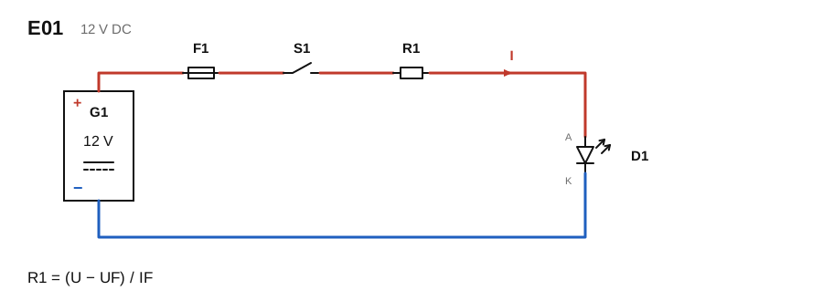
Start with a low-voltage circuit such as 12 V DC. An LED is a diode: it conducts in one direction only. The anode (A) faces the plus side and the cathode (K) faces the minus side; with reversed polarity it does not light and can even be damaged. An LED does not limit its own current: once the forward voltage (UF) is reached the current rises steeply, so a series resistor or a constant-current driver is needed, otherwise the LED is damaged. The fuse (F1) protects the conductor and the supply side against a short circuit; it does not limit the LED current.
Read the diagram in the direction of current, from plus to minus: G1 power supply → F1 fuse → S1 switch → R1 resistor → D1 LED (anode → cathode) → back to the minus of G1.
Calculate the resistor from the data sheet: R1 = (U − UF) / IF. For example, with a 12 V supply, UF ≈ 2 V and IF = 20 mA, R1 = (12 − 2) / 0.02 = 500 Ω; choose the next higher standard value (510 Ω), which gives about 19.6 mA. The resistor dissipates about 0.2 W, so use a ½ W resistor.
Designations: G1 12 V DC power supply, F1 fuse, S1 switch (make contact), R1 resistor, D1 LED, I direction of current. The diagram is not suitable for wiring a mains-voltage LED driver.
2. Connecting a motor: separate power and control functions
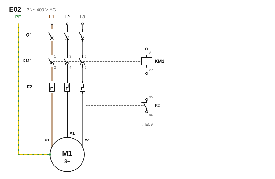
Starting a three-phase motor is not simply connecting three conductors. The power circuit (L1, L2, L3 → motor) and the control circuit (the contactor coil, the push buttons) are separate circuits. The diagram shows the power circuit of a direct-on-line start: Q1 protects against short circuits and isolates, the main contacts of contactor KM1 switch the motor, thermal overload relay F2 monitors prolonged overload, motor M1 receives the three phases at terminals U1, V1, W1, and the protective conductor (PE) goes to the motor frame. The contactor coil (A1–A2) and the auxiliary contact of F2 (95–96, normally closed) belong to the control circuit: on the right of the diagram only their link is indicated, and section 9 shows how they are wired.
With a motor-protective circuit breaker that has both thermal and magnetic releases, a separate F2 can be omitted because the breaker also protects against overload. Set the trip value to the rated current on the motor rating plate. The utilisation category of the contactor (usually AC-3 for motors), the starting method, the emergency stop, the phase sequence (it decides the direction of rotation) and the choice of protective devices depend on the motor rating plate and the designer.
Designations: Q1 short-circuit protection (motor-protective breaker or miniature circuit-breaker), KM1 contactor (main contacts 1–2, 3–4, 5–6; coil A1–A2), F2 thermal overload relay (auxiliary contact 95–96), M1 three-phase motor (3~), U1 V1 W1 motor terminals.
3. Reading a circuit diagram: a lamp controlled from two locations
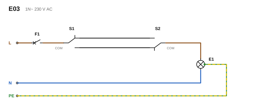
With two-way switching, two changeover switches control one lamp. The phase (L) reaches the common (COM) terminal of S1 through the miniature circuit-breaker F1. Two traveller conductors run between the two other terminals of S1 and the matching terminals of S2. From the common terminal of S2 the conductor goes to the lamp (E1). The neutral (N) connects directly to the lamp. Flipping either switch changes the state of the lamp: when both switches are on the same traveller the circuit is closed and the lamp is on; when they are on different travellers the circuit is open. The diagram shows the off state.
The switches break the phase, not the neutral, so with the lamp off its lampholder is not live. The protective conductor (PE) is a separate continuous conductor: it goes to the luminaire body and must not run through a switching contact. For control from three or more locations, an intermediate (cross-over) switch is inserted into the travellers between the two changeover switches.
Reading order: first identify the supply and the load, then the switching elements, then follow the phase, the neutral and the protective conductor separately. Conductor colours: the phase is usually brown (or black, grey), the neutral light blue and the protective conductor green-yellow; travellers have no colour of their own, but do not use light blue or green-yellow for them. Colours in the diagram are illustrative only; use the design, the equipment documentation and the applicable requirements for actual identification.
Designations: F1 miniature circuit-breaker, S1 and S2 changeover switch (COM = common terminal), E1 lamp, L phase, N neutral, PE protective conductor.
4. Push button and relay: why is control separate?
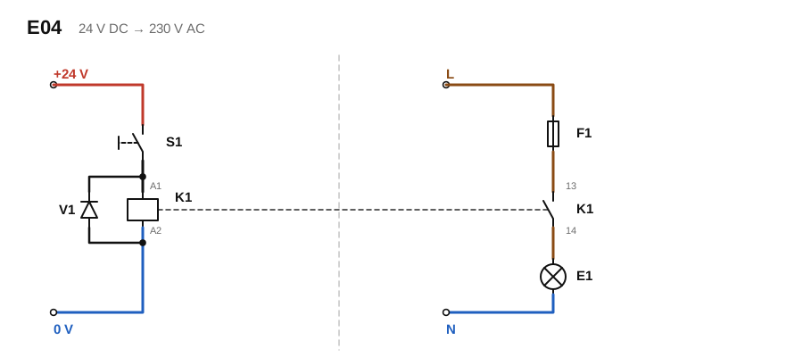
A small control signal operates the relay coil (here 24 V DC), while its contact switches a separate circuit, galvanically isolated from the coil (here a 230 V lamp circuit protected by F1). The push button therefore switches only the small coil current, not the load current. While you hold S1 down, K1 pulls in and the 13–14 contact closes; when you release it, K1 drops out. For lasting operation a latching (self-holding) circuit is needed (section 9).
A freewheeling diode (V1) is connected across a DC coil: its cathode faces the plus side, so it is reverse-biased in normal operation, and when the coil is switched off it absorbs the inductive voltage spike that could damage the control. Many relays and relay modules already contain one; the diode is polarity-sensitive and causes a short circuit if connected the wrong way round. Choose the voltage, current and switching category of the contact for the actual load (for an LED driver or an inductive load the inrush current also counts); the coil voltage matches the control circuit. The insulation level between the 24 V control circuit and the 230 V load circuit is guaranteed by the relay data sheet.
Designations: S1 push button (make), K1 relay (coil A1–A2, contact 13–14 make), V1 freewheeling diode, F1 fuse, E1 load (lamp). The drawing shows two separate circuits; the dashed line is the mechanical link between the coil and the contact.
5. Star-delta: not every motor starts the same way
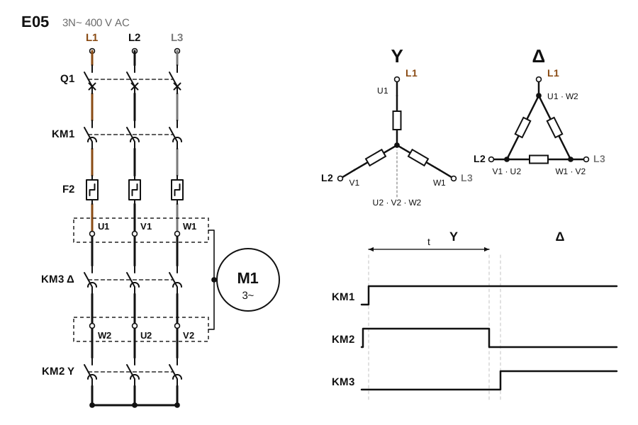
For larger motors with an easy start (for example fans and pumps), star-delta starting reduces the starting current. It requires a six-terminal motor whose windings can run in delta at the line voltage of the supply. This can be read from the rating plate: on a 400 V supply a "400 V Δ" motor (for example 400/690 V Δ/Y) is suitable, while a motor with a 230/400 V Δ/Y plate can only run in star at 400 V and is therefore not suitable.
In the diagram: the line contactor KM1 connects the supply to terminals U1, V1, W1. Star contactor KM2 joins terminals W2, U2, V2 (the star point): the motor starts in star, the windings receive 1/√3 of the line voltage (about 58 %, about 230 V on a 400 V supply), and both the starting current and the starting torque are about one third of a direct start. According to the timing chart, KM2 closes slightly (a few tens of milliseconds) before KM1 so that it does not switch a loaded circuit, and after time t (set on the timer relay to suit the run-up of the machine) KM2 drops out and, after a short dead time, delta contactor KM3 closes: it joins terminals U1–W2, V1–U2, W1–V2 and the motor runs in delta at full voltage.
KM2 and KM3 must never pull in at the same time: together they would short-circuit the phases, so electrical interlocking is mandatory, and mechanical interlocking is common and recommended. The torque in star is low, so the method is unsuitable for machines that start under load, and the changeover causes a current and torque surge. Here the overload relay F2 is in the supply branch, set to the rated motor current; if it monitored the phase current (in series with the winding), it would be set to about 58 % of the rated current. The contactors are sized from the manufacturer's tables.
Designations: Q1 short-circuit protection, KM1 line, KM2 Y star, KM3 Δ delta contactor, F2 overload relay, M1 six-terminal motor (U1 V1 W1 and W2 U2 V2), t changeover time.
6. LED strip: several sections are not one long LED

An LED strip needs a constant-voltage supply (here 24 V DC), and the rated voltage of the power supply must match that of the strip. The strip is made of ready-made branches (in the drawing a resistor and an LED in series) that are in parallel between the positive and negative rails, which is why it can be cut at the cutting points marked by the manufacturer. For simplicity the drawing shows one LED and one resistor per branch; on a real 24 V strip several LEDs are in series with one resistor in each branch. Polarity: plus to the plus rail, minus to the minus rail.
On a long strip the resistance of the conducting rail causes a voltage drop and the far end becomes dimmer. Sections should therefore be fed independently, in parallel (not chained end to end), and a long section from both ends. A higher-voltage (24 V) strip draws less current for the same power, so the voltage drop is also smaller. In the diagram, sections LS1 and LS2 each get their own pair of conductors from the same power supply G1, each with its own fuse (F1 and F2).
Calculate from the power: I = P / U. For example, 5 m of a 14.4 W/m strip is 72 W, which is 3 A at 24 V. The power supply should have a sufficient reserve above the total power of all strips, and the rated current of the fuse should be above the section current but below the current-carrying capacity of the conductor. The maximum feed length and the data of the strip come from the manufacturer's data sheet; do not operate it coiled up, as it overheats.
Designations: G1 24 V constant-voltage power supply, F1 and F2 fuse, LS1 and LS2 LED-strip sections.
7. Single-line diagram: the logic of the board in one line
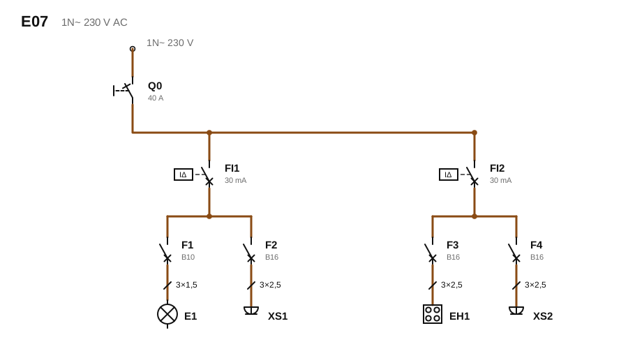
A single-line diagram draws a multi-conductor circuit (here L, N and PE) as one line, and shows not the physical installation positions but the order of protective devices and loads. In the diagram: supply (1N~ 230 V after the energy meter) → Q0 main switch (isolation) → two residual-current devices (FI1, FI2, 30 mA) → behind them the miniature circuit-breakers (F1–F4) → final circuits: E1 lighting, XS1 and XS2 sockets, EH1 hob. On a cable, the slash is followed by the number of conductors and the cross-section (for example 3×1.5: three conductors of 1.5 mm²).
Why two residual-current devices? One shared device tripping de-energises the whole flat; two devices limit that. B10 and B16 are the tripping characteristic (B) and the rated current (10 and 16 A) of the miniature circuit-breaker. The example values (B10 and 1.5 mm² for lighting, B16 and 2.5 mm² for sockets) are only indicative: the actual value depends on the load, the conductor length, the installation method and the requirements. The EH1 hob example applies to a single-phase hob of at most about 3.6 kW; a larger hob is normally connected to a separately sized three-phase circuit.
Designations: Q0 main switch, FI1 and FI2 residual-current device (IΔ: operates on the differential, that is fault, current), F1–F4 miniature circuit-breaker, E1 lamp, XS1 and XS2 socket, EH1 hob (fixed load).
8. Timer relay: switching after a set delay
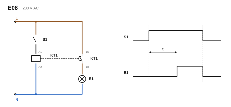
On a control signal, the coil of the timer relay (KT1) starts timing and switches its contact after the set time t. The diagram shows an on-delay relay: when S1 closes, KT1 is energised, after time t the delayed 15–18 make contact closes and lamp E1 switches on. When S1 is released the coil is de-energised and the contact opens at once. The timing chart shows this: switching on is delayed, switching off is not. The small arc on the contact is the symbol for delay; the concave side of the arc faces the delayed movement, here closing.
Such a relay is used, for example, to start machines in sequence, to time the star-delta changeover (section 5) or to delay the restart of a compressor. An off-delay relay keeps its output on for time t after switching off; that is the typical solution for run-on ventilation (for example a bathroom fan) and for staircase lighting. Multi-function timer relays can also do these and pulse and cycle functions; always select the function according to the device type.
Designations: S1 control contact (here a signal source held closed), KT1 timer relay (coil A1–A2, delayed make contact 15–18), E1 the switched load, t the delay time.
9. Contactor latching: START does not stay pressed
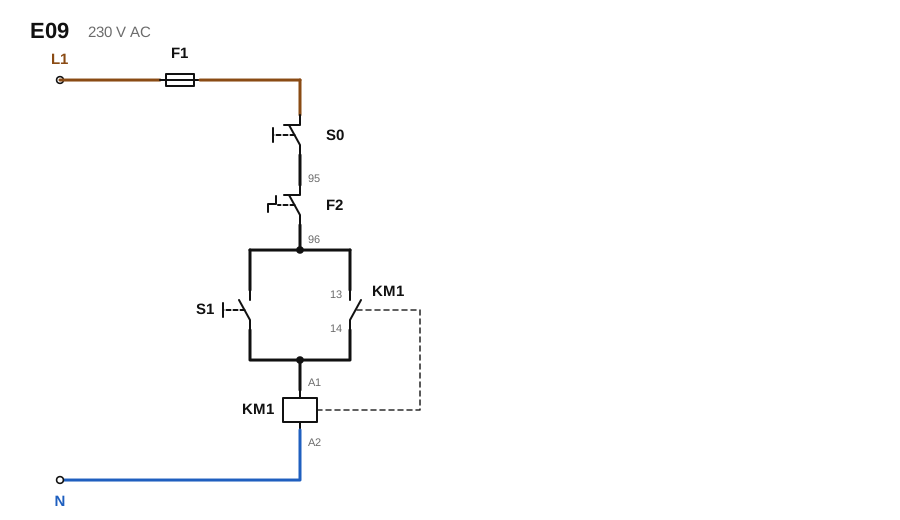
In latching, a short press of the START (S1, make) push button pulls in contactor KM1. The auxiliary contact 13–14 of KM1 closes in parallel with S1 and takes over supplying the coil, so S1 can be released. The STOP (S0, break) contact and the 95–96 break contact of the overload relay F2 are in series with the coil: either one interrupts the circuit, KM1 drops out, the auxiliary contact also opens, and the motor restarts only after a new START.
STOP is a break (NC) contact because even a broken wire or a loose terminal then leads to the stopped, safe state: a fault in the control circuit must not keep the motor running. The switching contacts are on the phase (L) side and the coil is on the neutral side, so an earth fault does not pull in the contactor. After a voltage failure a latching circuit does not restart by itself, which is desirable; with a permanently closed switch (two-wire control) the machine may restart by itself when the voltage returns. This is control logic that must be designed together with the actual protections, interlocks and protection against unexpected restart, according to the risk assessment of the machine.
Designations: F1 control-circuit fuse, S0 STOP (break), F2 overload relay 95–96 (break), S1 START (make), KM1 contactor (coil A1–A2, auxiliary contact 13–14 make).
10. Motion-sensor light
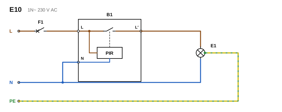
The motion sensor (B1, here PIR, passive infrared) switches the phase conductor of the lamp with its internal switching contact (L → L′). It has three terminals: L and N supply the sensor itself, so it needs a permanent phase and a permanent neutral; L′ is the switched output that goes to the lamp. The other terminal of the lamp connects to the neutral, and the protective conductor goes to the luminaire body. If the switch box has no neutral conductor (only the phase and the conductor to the lamp, as in a conventional switched installation), a three-wire sensor cannot be connected: a two-wire sensor is needed.
When learning, separate in your mind the detection (PIR), the decision (the electronics of the sensor: sensitivity, delay, light threshold), the switching (L′) and the load; that makes most automatic lighting tasks understandable. The load rating of the output, the conditions for LED or inductive loads (minimum load, inrush current) and any manual override are always given by the device documentation.
Designations: F1 miniature circuit-breaker, B1 motion sensor (PIR; L, N, switched L′), E1 lamp, L phase, N neutral, PE protective conductor.
11. A 24 V sensor on the controller input
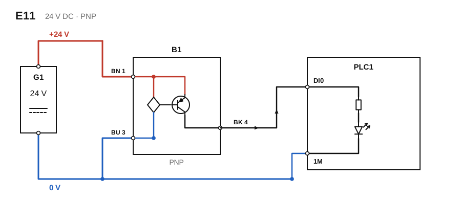
A three-wire industrial sensor uses separate supply conductors and a separate signal conductor. The usual conductor colours and M12 connector assignment are: brown (BN, terminal 1) = +24 V, blue (BU, terminal 3) = 0 V, black (BK, terminal 4) = output signal. The sensor takes its power from the power supply G1; the PLC reads only the signal (the black conductor).
A PNP sensor switches its output to +24 V when active. The signal current then flows through the PLC input and returns to 0 V, so the common point of the input (here 1M) connects to 0 V, and the 0 V of the sensor, the power supply and the input is common. An NPN sensor, by contrast, switches its output to 0 V and needs an input of the opposite polarity. The input type, the voltage level and the load rating of the sensor must be matched according to the data sheets of the PLC and the sensor; a mismatch leaves the input not working or can damage the equipment.
Designations: G1 24 V DC power supply, B1 PNP sensor (BN, BU, BK), PLC1 controller (DI0 digital input, 1M the common point of the input), I signal-circuit current.
12. Reversing a motor
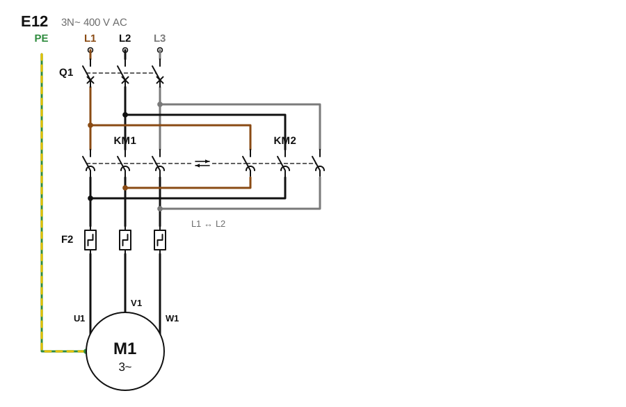
On a three-phase motor, swapping two phases reverses the direction of rotation. In the diagram KM1 connects phases L1, L2, L3 straight to terminals U1, V1, W1 (forward), and KM2 swaps phases L1 and L2 (reverse: L1 → V1, L2 → U1, L3 → W1). Both contactors are fed from the same supply, so if they pulled in together there would be a short circuit between the phases. KM1 and KM2 must never operate together, which is why interlocking is not optional.
The interlock must be both electrical (a break auxiliary contact of one contactor, for example KM1 21–22, in series with the coil of the other contactor) and, preferably, mechanical (a mechanical element linking the two contactors; in the diagram the double arrow between the dashed lines). Reversing while running would cause a large current and torque surge, so the control normally allows a start in the opposite direction only after standstill. The drawing shows the power circuit; the control (a separate START for each direction and a common STOP) should be completed as in section 9; limit-switch protection, braking and protection against unexpected restart are part of the safety design of the machine.
Designations: Q1 short-circuit protection, KM1 forward, KM2 reverse contactor, F2 overload relay, M1 three-phase motor, ⇄ between the two contactors is the mechanical interlock.
13. Why split into several circuits?
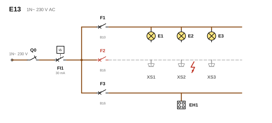
In a distribution board, loads of different purposes typically start on separate protective branches. In the diagram, after the main switch Q0 and the residual-current device FI1 there are three circuits: F1 lighting (E1–E3), F2 sockets (XS1–XS3), F3 hob (EH1). If an overcurrent or short circuit occurs in the socket circuit (the lightning symbol), only F2 trips: the lighting and the hob stay in operation (in the diagram the tripped circuit is dashed grey).
The benefit is easier fault finding (you can see which circuit is faulty), more targeted protection (each circuit gets a circuit-breaker sized for its own conductor and load) and better continuity of operation (a socket fault does not leave the flat in the dark). Large loads (hob, oven, boiler, air conditioner) usually get their own circuit. The residual-current device FI1, however, trips on residual (fault) current, that is, the difference between the phase and neutral currents, for example in an earth fault or leakage, and switches off every circuit behind it; this is why larger boards use several residual-current devices (see section 7). The exact grouping is made from the design, the loads and the applicable requirements.
Designations: Q0 main switch, FI1 residual-current device, F1–F3 miniature circuit-breaker (B10, B16 are the characteristic and the current), E1–E3 lamp, XS1–XS3 socket, EH1 hob (a smaller single-phase example).
Practice questions
- Why does the LED circuit need current limiting, and how do you calculate the resistor?
- What is the difference between the switching task of a contactor and the task of overload protection?
- Why must PE not be routed through a switch?
- Why is a break (NC) contact used for the STOP button?
- Why can the star and delta contactors, or the forward and reverse contactors, never pull in at the same time?
If you want to document a design clearly, continue with symbols and symbol sets and then the wires and circuits chapter.